Can AI design an analog chip? I built a radio to find out
Radio has always felt like a kind of magic to me, and I’ve wanted to build one on a chip for years. In my 2024 review I set myself a goal: a pair of Tiny Tapeout projects that can send and receive data with just a couple of short wire antennas.
I made some progress - a ring oscillator, an R2R DAC, level shifters and amplifiers - but that still left a lot missing for a working radio.
A few weeks ago I finally designed it, with an AI agent doing most of the work. About 700 prompts over a week. It’s fast and seriously impressive, but it also made mistakes I only caught because I’ve been doing analog for a few years. One of them would have left a quarter of the radios missing their spec.
The chip goes to the fab in November, so everything here is simulation. I’ll only count it as a win when the chips come back and talk to each other.
Can AI actually do analog?
If you’ve studied analog chip design, you’ve probably heard of Behzad Razavi, the UCLA professor whose textbooks a lot of us learnt from. Earlier this year he tested AI on his own analog design questions, and the best model got about half of them right.
Zhishuai Zhang at ETH Zurich has turned those kinds of questions into a benchmark that makes it easy to test different models. In just a few months the leaderboard had changed completely, with Claude Opus in third place at 95%.
The benchmark doesn’t allow tools, because it’s testing how well the models reason. But to build a real radio I wanted the best results, so I re-ran the questions and gave the agent ngspice to check its answers. Claude Opus 5.5 on max effort came out on top, with 96.5% (see my results, as of 19th October).
Exam questions are one thing - could it help me build a radio?
The radio
Two Tiny Tapeout demo boards with the same chip, a couple of 16.5 cm wires on each, and no other parts. Set the same code on the DIP switches of both boards, press reset on the transmitter, and if the receiver hears its code it toggles an LED.
The transmitter switches an on-chip ring oscillator on and off - this is called on-off keying (OOK). I was aiming for 433 MHz like a garage door opener, but in the end I decided not to tune the ring, so each chip will land somewhere around 450 to 470 MHz. The receiver uses an 80 dB amplifier chain, a log detector and a comparator to pull the ones and zeros back out, and a Gold code correlator to find the transmitter’s pattern even in a weak signal.
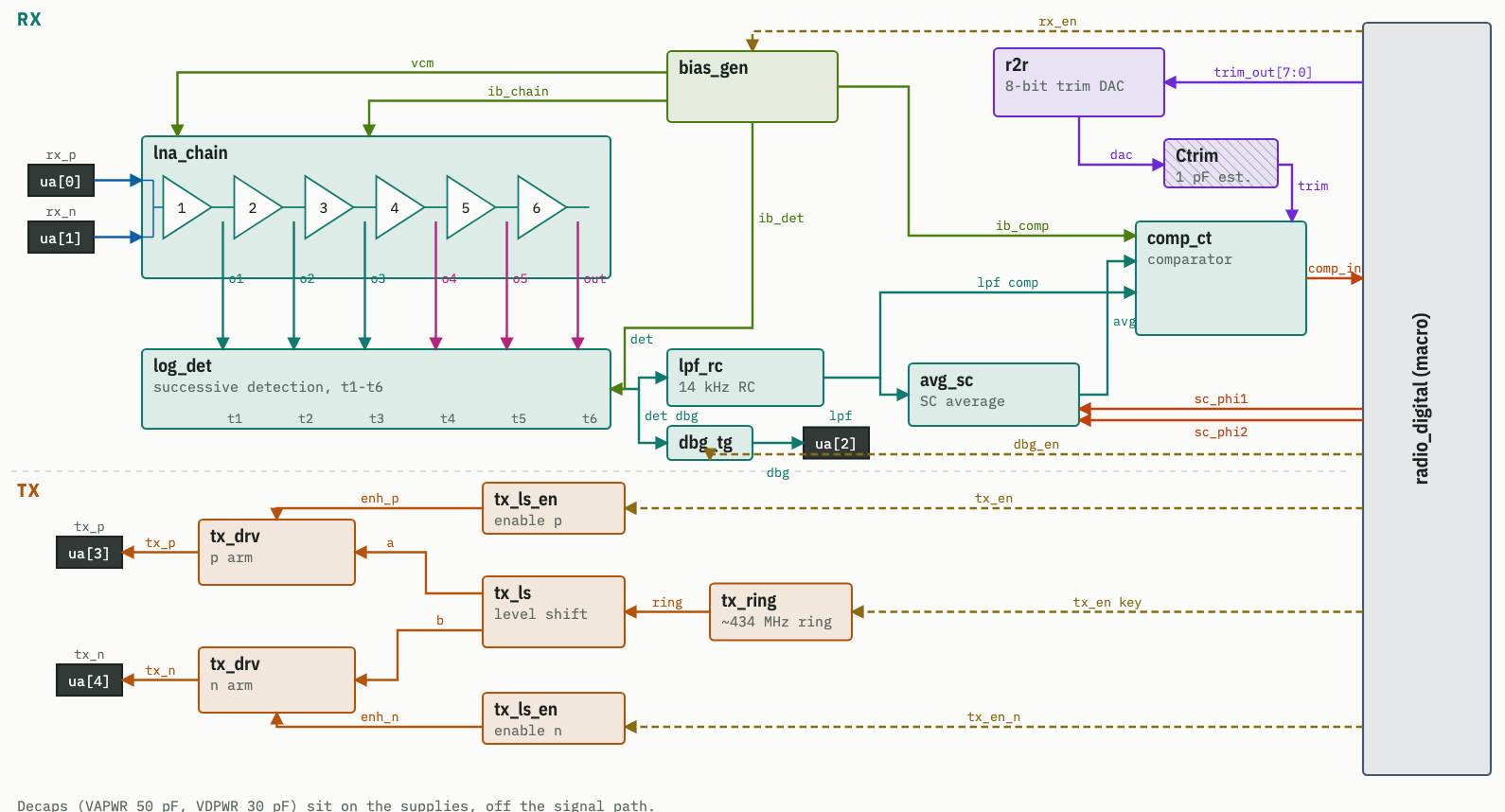
The best way to see how it works is the interactive radio explainer. You can click through every block of the transmitter and receiver, drag the received power slider and watch the signal change, and open each block’s layout in 3D. All the data comes from the simulations of the actual design.
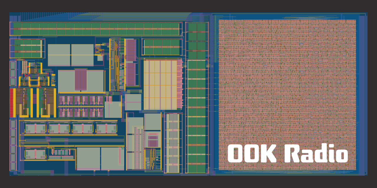
My favourite parts are the amplifier chain, where you can see each stage take over in turn as the signal gets smaller, and the comparator, which uses the average of the signal as its reference so it can still find the ones and zeros at very low levels.
How I worked with the agent
Specification. I gave it the Tiny Tapeout specs and asked for ideas. Its first plan would only have worked over about a metre, because it took the 50 MHz recommended maximum for the pins too literally. I already knew my ring oscillator chip ran at 500 MHz, so we did an experiment instead: wire antennas, my scope and some firmware to switch the ring on and off. The measurements from my lab changed the whole design. Before drawing a single transistor, we had a Python model of the receiver that worked on real recorded signals.
Schematics. This is where I needed the most help. I’d built ring oscillators and level shifters before, but never a comparator, a bias generator or an 80 dB amplifier. It drew those, and every block was simulated against the Python model. The first schematics had no wires at all, but asking for “textbook style” made them much easier to review.
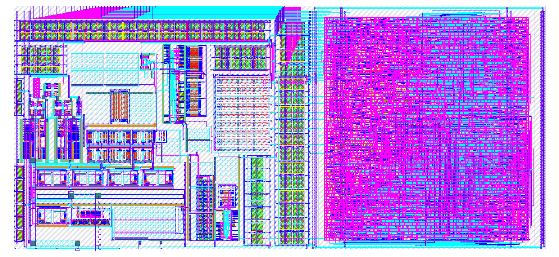
Layout. Harald Pretl had good results using KLayout with parametric cells, so the agent builds known-good transistors from code and wires them with its own channel router. 12 blocks that would have taken me up to a day each were done in 3 or 4 hours, each one checked against its schematic and re-simulated with parasitics. After a couple of rounds of feedback, I don’t think I could have done much better. Have a look at the transmitter’s output driver in 3D, with its power rails along the top and bottom.
Floorplanning. This was the agent’s weakest area. Its first attempts weren’t great, so I asked it to build me a drag and drop tool with a checklist of rules (keep the amplifier away from the digital pins, for example). It took about 15 minutes to make. I arranged the blocks, exported the positions, and the agent did the top level routing.
Verification. On my previous analog designs I’ve mostly checked the typical corner, plus Monte Carlo if I’m feeling fancy. This time we went all out: every process corner, supply voltage and temperature. A full run took 10 hours on Ed’s 32 core server (thanks Ed!). It found that at room temperature a quarter of the radios would miss the -92 dBm sensitivity target, because the comparator’s trim range was too narrow. We fixed the comparator, gave up a little sensitivity, and now 99% of radios reach the spec in simulation. I would never have caught that.
Where it went wrong
There were plenty of times it was confidently wrong:
- The floorplanning rules said to keep the transmitter far from the receiver. Sounds sensible, but this is a half duplex radio - when it’s receiving, the transmitter is off. Removing that bogus rule made the floorplan much easier.
- I could see straight away that the power wiring was too thin. Instead of just saying “fix it”, I asked it to benchmark the power network first: impedance at 433 MHz, voltage drop and electromigration. The transmitter driver supply had about half the metal it needed. After the fix it re-ran the same benchmark and the results were much, much better.
- Mitch Bailey took a look at the LVS setup and found that it could pass even when device sizes were wrong. Now any property mismatch fails the check.
I’d guess this would have taken me about two months of full time work. But right now, somebody needs to be driving it who knows when it’s wrong.
My reservations
I also have reservations about generative AI in general, mostly about how a lot of the training data was taken without permission.
And it seems to work best for experts, who can spot where it’s going wrong. If you’re a beginner who always accepts the next suggestion, you can end up with something that looks like it works but won’t in the real world. The experts I know are really enjoying these tools - but how do you become an expert if we all just push the one-shot button?
What I’d tell you
If you already have some expertise, it’s worth trying these tools to see how far you can go and how much time they save.
If you’re a beginner, take advantage of having an incredibly patient teacher. When you don’t understand something, keep asking until you could explain it to someone else. Don’t give up the chance to learn just to get it done.
I learnt a lot on this project. Gold codes, the same trick GPS uses to pull data out of very weak signals. And comparator offset: I didn’t know a comparator can get stuck outputting all ones or all zeros when the signals are very close. The fix is a trim from my old R2R DAC, with digital feedback that keeps the output an even mix of ones and zeros, as the Gold code should be. That tunes out the offset and gains a little extra sensitivity.
What’s next
The radio is submitted to the next SkyWater shuttle, and the chips are due back around May or June. I’ll probably test them on a live stream, so subscribe on YouTube if you don’t want to miss it. I’m also planning a full walkthrough video of how the radio works.
I’m also interviewing two of my mentors, Professors Harald Pretl and Carsten Wulff, who have been using agents for analog design for longer than I have. If you’ve got questions for them, leave them in the YouTube comments.
Everything is open source on GitHub, including all the prompts.
I could only spot where the agent went wrong because I’ve spent years building intuition for analog. If you want to build that intuition yourself, that’s what my Zero to ASIC analog course is for.
This is an experimental, uncertified transmitter on an untuned frequency. If you get one of these chips, check the frequency with an SDR before transmitting, and check your local radio rules. See the bring-up guide for details.